This La-5 file contains three scenes:
- Airborne: aircraft is placed on the background of the clouds. This scene I have used for the short
animation of the pilot weaving his hand. It contains frames from 1 to 300. Uses some IPO curves for
the pilot's body movement (hand, head), for the control surfaces, and for the propeller axis.
The propeller axis is a parent of two assemblies: static propeller blades, and "dynamic" propeller disk. Both are rotating with it.
You can select one of this objects to be visible, by switching on or off their layers (see below, the
layers content description). In general, static blades looks good on the airborne still images, when
you turn the Renderer MBLUR option on, and set the highest oversampling (Renderer OSA option - to 16).
They are "blurred" on the result renderings - like on the photos.
You cannot use motion blur effect in animations. For this purpose I have utilized a nearly transparent disk, which
has the diametr of the propeller, and also rotates (it makes better the impression of its "dynamic" nature). In fact, human
eyes are not a photo camera. We see the rotating blades as such disk, not as the blurred blades.
There are two cameras: Camera.Tracked, intended for the still images, which follows the location of "dummy"
Camera.Target object. (Use it to set the focus.) Camera.Static, on the other hand, is created for the airborne animation. It does not
track anything, because it has to "catch" properly the random movements of the airplane in the air.
There are four lights. Name of one of them - Clouds - sounds somewhat improper. It is just mimicking the
sunlight reflected from the white clouds.
- Ground: scene of the aircraft on the ground. This scene is intended for the still images. It contains one camera, tracking the location
and orientation of the "focus" object - Camera.Target.Ground. There is an Earth plate, which is a parent of the Grass mesh.
Grass is utilizing a static particle system to create impression of some grass blades. I wanted them to "slash" a little bit the shadow
of the airplane, making it more realistic on the grassy background.
This effect is not so sound in Blender 2.45, but much more better in 2.46.
- Cockpit: scene created to take some cockpit pictures. I have worked hard on all these small details, so I think they are worth
of a rendering! Actually it contains three lights: Sun.Inner, which cast the shadows, Hemisphere.Cockpit, responsible for the ambient light,
and Flash, added to expose more details in the cockpit.
Flash light is directed along the camera sight - because it is the child of Camera.Inner object.
Beware: if you set Flash light energy too high, your renderings will be "overexposed", like the real photos!
In subsequent text I have used ordinal numbers to reference Blender layers. These ordinals are assigned as follows:
| 1 |
2 |
3 |
4 |
5 |
|
6 |
7 |
8 |
9 |
10 |
| 11 |
12 |
13 |
14 |
15 |
16 |
17 |
18 |
19 |
20 |
Content of the layers:
- Inner skin, ribs and longerons of the fuselage;
- Elements of the engine system (inlets, exhaust stacks, coolers), that are visible from
a long distance;
- Wheels;
- Undercarriage legs;
- Propeller, static version (not usable for the flight animations, usable with the
“motion blur” option for the airborne still images);
- Forward ring of the engine cowling;
- Propeller, „disc“ version. (use this layer or the layer 5, exclusively);
- The pilot figure (in the Airborne scene, only). Placeholders (empty objects) for
some textures, mapped using “object” mode (national insignia, maintenance labels) – turn
on for animations!
- Artificial objects, which are the “gears” of the moveable parts. For example – discs,
used to control the rotation of engine cooling louvers. Keep always off for the
renderings;
- Artificial objects - handles, controlling the moveable parts, and the camera target.
Armatures of the pilot and main undercarriage legs. Keep always off for the renderings;
- Main body (fuselage, wings, stabilizers);
- Control surfaces: ailerons, rudder, elevator, flaps, slats, and their actuators;
- Canopy frame, antenna mast and wires;
- Canopy glass;
- Undercarriage wheel doors;
- Engine;
- Engine cowling;
- Cockpit details, which can be important for the pictures from the outside;
- Cockpit details, which can be discarded for the pictures from outside;
- Cameras and lights;
The La-5 model contains some scenes. The model objects, that can be shared between many scenes,
are identified by a three-digit number prefix. The name of such object is built from following
segments, separated by a dot:
- part number prefix: 3 digits.
- human name of the part;
- optional elements: “side” suffix (“L” = left, “R” = right), or enumeration number (034.Louvre.01, 034.Louvre.02, ….)
BEWARE: "right" and "left" have reversed meaning here. One day, at the begining,
I named the sides looking at the front view, not from the cockpit! I noticed it a few days later,
but finally I have decided to continue this convention, in this model.
Sometimes many objects, that forms a single “assembly”, have the same part number prefix.
They are differentiated by the human name, only. For example – all objects that are used
in the pilot figure have the same prefix “000”.
There are also empty objects, that are just placeholders for the texture “stickers”
(national insignia, or maintenance labels). They have the same part number and
human name - like their parent objects, that the texture is laid on. Their name has additional,
third segment, which indicates the index of the material, that uses the corresponding texture.
For example – 012.Body.10.L object.
Few elements, that are specific for the particular scene (lights, cameras, some
environment like ground) have not any numeric prefixes.
There are dedicated materials, created for a single object (more exactly: its mesh), or
general materials, that are shared between many similar objects (like “Steel”, or “Wood”).
Dedicated materials have their names build from following segments:
- 3-digit prefix, identical to the object they belong. (for example, all materials of the
“012.Body” object also have the “012” prefix);
- “conceptual” name of the material: UCamuflage for the camouflage of the upper surfaces,
LCamuflage for the camouflage of the lower surfaces. For example – 039.LCamuflage;
- optional 2-digit index of the material in the mesh, if it has more than one material
assigned. For example – 012.UCamuflage.01 is the upper camouflage of the part of
the 012.Body mesh, assigned to material index 01. Similar, 012.LCamuflage.02 is the lower
camouflage of the part of the 012.Body mesh, assigned to material index 02. In fact the 012.Body
is separated between highest number of the material parts – 15!;
- optional letter, that indicates the side: “L” for the left, “R” for the right. For example
– 039.UCamuflage.R. It is the name of the material assigned to the 039.Cowling object, the upper
camouflage of the right side;
The general materials, which can be shared between many different objects, have simple,
“human” names, without any numerical prefix or suffix. For example – “Wood”,”Glass”,”Inner”
(for the inner surfaces).
There are many (too many, I know ….) textures in this model. I will reduce it in my next work.
In most materials you can find textures, emulating to following effects:
a bump map, that creates the rivets, clefts, and other mechanical joints on the object surface;
a transparent color map, that creates the dirt, accumulated during aircraft maintenance;
a transparent color map, that creates the darker color of the camouflage splashes (the
lighter color should be the color of the material, itself). This element is required for the
upper camouflages – when it contains the splashes in another color.
It would be possible to join the texture of the dirt, and texture of the camouflage into a single
texture. They are kept separated for easier changes in the camouflage scheme. The idea is, that it will
be enough to change the base color of the material, and the camouflage splashes texture, to
create another case of the painting. You do not need to touch the things that are common to all
airplanes of the same type: the panel lines, rivets, and maintenance dirt.
The name of the dedicated texture contains:
- 3-digit prefix, identical to the object they belong. (for example, all textures of the
“012.UCamuflage.01” material also have the “012” prefix);
- “Conceptual” name of the texture: “Rivets” or “Clefts” for bump maps. “Dirt” for the
maintenance dirt. “Camuflage” for the other color splashes. For example – 039.Camuflage;
- optional 2-digit index of the material that the texture belongs to.
For example – 012.Dirt.01 creates the dirt on the 012.Body mesh, assigned to material index 01;
- optional letter, that indicates the side: “L” for the left, “R” for the right.
For example – 012.Camuflage.07.R. It is the name of the material assigned to the 012.Body
object, the upper camouflage splashes of the right side;
Like the general materials, there are also general textures, which are shared among many objects.
Their names are simple – “Linen”, “Wood”, “Glass dirt”.
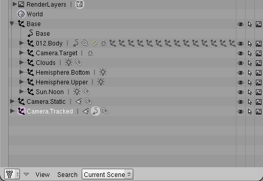
There is an object named Base, at the root of the hierarchy. It was created specially
for the purpose of airborne animation, and contains the root of the whole airplane – 012.Body
object. It also contains all lights (Hemisphere.*, Sun, Clouds),
and a special object, which is not rendered – Camera.Target. One of the
cameras - Camera.Tracked – is tracking the location of Camera.Target. (I
have practiced, that such pair allows you quickly adjust the view from
camera, in the most intuitive way. Camera is just always “looking” at its
target!).
The Base contains all lights, because in the airborne animation the airplane had to
“jump” a little bit on the screen. It should look like the movements between
two airplanes in the air (one with camera, and the other with the target). The
shadows should not move during these “jumps” – so they are “fixed” to the same,
invisible, frame, that keeps the airplane.
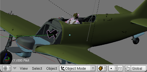
- Select in the 3D View the object, for which you would like to find the parent and children, in the hierarchy.
For example – the pilot figure:
- From lower left corner of the 3D View window read the name of selected object. In this case it is “000.Pilot”:
- Localize this object in the hierarchy, and check, if there is not any unexpected thing there.
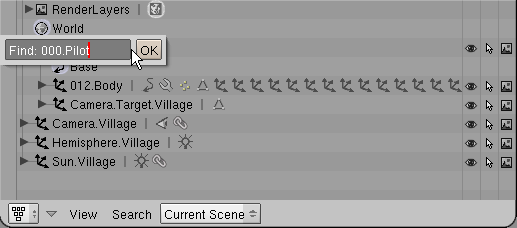
In Outliner window:
- select the Base or 012.Body object: they are at the “root” of the model hierarchy;
- use Search=>Find command, (or just press [F]), and look for the object name:
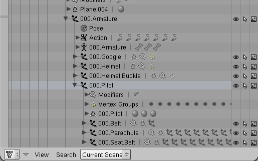
- Revise the parent of found object – are there any other objects around?
In case of the 000.Pilot, you can see that it belongs to 000.Armature, which is not visible in
3D View (because it is on the layer 10, dedicated for “special” objects).
Of course, the armature should always accompany the pilot. What is also surprising at the first
glance, is that the helmet, goggle and even the buckle at goggle strip (000.Helmet.Buckle) does
not to belong to the 000.Pilot itself, but to the armature! Why? Because they should go with the
pilot’s head, when it turns around. The turning of the head is controlled by the neck bone,
form the armature. So, all these things, that are on the head, have their parent in the 000.Armature.
More precisely – have parent in the same neck bone, to which the vertices from the pilot’s head
are assigned.
When you have troubles to find in the 3D View an object:
- Select it in the Outliner;
- Find its layer - in the Buttons window, on the Draw panel (one of the Objects panels);
- Turn all other layers off - you should see it, somewhere!;
Conclusion: if you want to do something with the pilot – move, rotate, or remove - you have
to deal with 000.Armature object, and all of its children. For example – to remove the
pilot from the current scene:
Select the 000.Armature object and make active. It is not enough to select it in the
outliner – you have to click it on the 3D view. Object is active, when its name is visible
in the lower left corner of 3D View;
Run Select=>Grouped=>Children command (from the 3D View window);
Run Object=>Delete (just [X]);